Wemos D1 Mini
Specifications:

A mini wifi board with 4MB flash based on ESP-8266EX
Wemos D1 Website
Datasheet
ESP8266 WeMos D1 Mini Tutorial
| Feature | Value |
|---|---|
| Microcontroller | ESP-8266EX |
| Operating Voltage | 3.3V |
| Digital I/O Pins | 11 |
| Analog Input Pins | 1(Max input: 3.2V) |
| Clock Speed | 80MHz/160MHz |
| Flash | 4M bytes |
| Length | 34.2mm |
| Width | 25.6mm |
| Weight | 10g |
Pins:
| Pin | Function | ESP-8266 Pin | Use |
|---|---|---|---|
| TX | TXD | TXD | (Serial). Also usable as GPIO1 if not using serial. |
| RX | RXD | RXD | (Serial). Also usable as GPIO3 if not using serial. |
| A0 | Analog input, max 3.3V input | A0 | |
| D0 | IO | GPIO16 | Momentary high on boot. No interrupt |
| D1 | IO, SCL | GPIO5 | nothing special. |
| D2 | IO, SDA | GPIO4 | nothing special. |
| D3 | IO, 10k Pull-up | GPIO0 | pull low during boot for flash mode. Other than that, usable as GPIO. |
| D4 | IO, 10k Pull-up, LED_BUILTIN | GPIO2 | pulled up during boot & internal LED (active LOW). |
| D5 | IO, SCK | GPIO14 | nothing special. |
| D6 | IO, MISO | GPIO12 | nothing special. |
| D7 | IO, MOSI | GPIO13 | nothing special. |
| D8 | IO, 10k Pull-down, SS | GPIO15 | fixed external pull-down (for boot). |
| G | Ground | GND | |
| 5V | 5V | - | |
| 3V3 | 3.3V | 3.3V | |
| RST | Reset | RST |
pinout
Wemos reference: Pin Functions

.jpg)
A0
The analog input of the ESP chip is limited to 1 volt max.
There is an internal divider on the Wemos D1 Mini that makes the range of A0= 0-3.3V
To find the external resistor value, use the online voltage divider calculator to find the total for R2, then subtract 220K.

I2C
I2C can be used to connect up to 127 nodes via a bus that only requires two data wires, known as SDA and SCL.
SDA => D2.
SCL => D1
interrupts
The pins D5, D6, D7 work without restrictions
D3 and D4 work, but can not be low on boot, otherwise the WEMOS freezes
D1 and D2 are used for I²C by default3
D0 (HPIO16) and D8 (GPIO15) have no support for interrupts
PWM
- PWM may be used on pins 0 to 15.
analogWrite(pin, value) enables software PWM on the given pin. Call analogWrite(pin, 0) to disable PWM on the pin. Value may be in range from 0 to 1023. 0 to 255 is normal on an Arduino board, as it's an 8 bit register, but ESP8266 uses software PWM so 1023 is full duty cycle.
SPI
SPI is much simpler than I2C. Master and slave are linked by three data wires, usually called MISO, (Master in, Slave out), MOSI (Master out, Slave in) and M-CLK.
M-CLK => D5
MISO => D6
MOSI => D7
(SPI Bus SS (CS)is D8.)
pins_arduino.h
/*
  pins_arduino.h - Pin definition functions for Arduino
  Part of Arduino - http://www.arduino.cc/
*/

#define PIN_WIRE_SDA (4)
#define PIN_WIRE_SCL (5)
//Wemos D1 Mini, pins D2(SDA) and D1(SCL).. Wire.begin(4, 5)

static const uint8_t SDA = PIN_WIRE_SDA;
static const uint8_t SCL = PIN_WIRE_SCL;

#define LED_BUILTIN 2
//                        = GPIO
static const uint8_t D0   = 16;
static const uint8_t D1   = 5;
static const uint8_t D2   = 4;
static const uint8_t D3   = 0;
static const uint8_t D4   = 2;
static const uint8_t D5   = 14;
static const uint8_t D6   = 12;
static const uint8_t D7   = 13;
static const uint8_t D8   = 15;
static const uint8_t RX   = 3;
static const uint8_t TX   = 1;

/*
Re: Wemos Board. Usable pins for general I/O?
TX, GPIO1: Serial Port. Also usable as GPIO if not using serial.
RX, GPIO3: Serial Port. Also usable as GPIO if not using serial.
D0, GPIO16: Momentary high on boot.
D1, GPIO5: nothing special.
D2, GPIO4: nothing special.
D3, GPIO0: pull low during boot for flash mode (connects to a push button).
D4, GPIO2: is pulled up during boot & internal LED (active LOW).
D5, GPIO14: nothing special.
D6, GPIO12: nothing special.
D7, GPIO13: nothing special.
D8, GPIO15: fixed external pull-down (for boot).
*/
Output Current Limit
When using a GPIO as output (i.e. to drive something such as an LED) it is important to note that the maximum output current is 12mA. (IMAX=12mA per Espressif datasheet) If you try and output more current than that, you run the risk of damaging the device. Since many LEDs are able to draw 20mA you should adjust your current limiting resistor to be 12mA or less. Using https://en.wikipedia.org/wiki/LED_circuit - R=(Vout-Vled)/I so (3.3V-1.8Vred) at 12mA = 125Ω min for a red LED.
Schematic
Shields
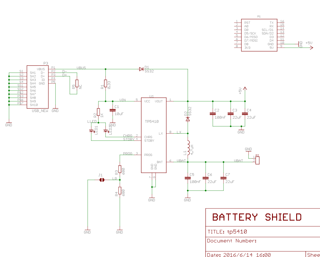
lithium (LiPo) Battery shield
lithium (LiPo) Battery shield, charging & boost Specifications:
| Features | |
|---|---|
| Charging Voltage | max: 10V, recommend: 5V |
| Charging Current | max: 1A |
| Lithium Battery voltage | 3.3-4.2V |
| Boost Power Supply | 5V(max: 1A) |
- Pins used
| D1 mini | Shield |
|---|---|
| 5V | 5V(max: 1A) Power Supply |
| GND | GND |
| Port | Usage |
|---|---|
| PH2-2.0MM (Port 1) | Connect to lithium Battery (normal 3.3-4.2V) |
| Micro USB (Port 2) | Charging port (normal 5V) |
| Green LED | lights when charging is completed |
| Red LED | lights when charging |
| J1 | setting max charging current, 0.5A or 1A. |
| J2 | Connect battery to A0 |
OLED Shield
Website


Sketch that uses this shield: ssd1306_64x48_i2c-ds18b20.ino
Wemos D1 Mini Notes
Most sample sketches show D2 and D1 as the SDA and SCL pins, but some show D3 and D5. Both work.
DS18B20 temperature sensor
Reference: Wemos mini DS18B20 temperature sensor example.
File:wemos-mini-and-ds18b20.png
#include <OneWire.h>

// OneWire DS18S20, DS18B20, DS1822 Temperature Example

OneWire  ds(D4);  // on pin D4 (a 4.7K resistor is necessary)


// =============================== setup() ===============================
void setup(void)
{
  Serial.begin(115200);
}


// =============================== loop() ===============================
void loop(void)
{
  byte i;
  byte present = 0;
  byte type_s;
  byte data[12];
  byte addr[8];
  float celsius, fahrenheit;

  if ( !ds.search(addr))
  {
    ds.reset_search();
    delay(250);
    return;
  }


  if (OneWire::crc8(addr, 7) != addr[7])
  {
      Serial.println("CRC is not valid!");
      return;
  }
  Serial.println();

  // the first ROM byte indicates which chip
  switch (addr[0])
  {
    case 0x10:
      type_s = 1;
      break;
    case 0x28:
      type_s = 0;
      break;
    case 0x22:
      type_s = 0;
      break;
    default:
      Serial.println("Device is not a DS18x20 family device.");
      return;
  }

  ds.reset();
  ds.select(addr);
  ds.write(0x44, 1);        // start conversion, with parasite power on at the end
  delay(1000);
  present = ds.reset();
  ds.select(addr);
  ds.write(0xBE);         // Read Scratchpad

  for ( i = 0; i < 9; i++)
  {
    data[i] = ds.read();
  }

  // Convert the data to actual temperature
  int16_t raw = (data[1] << 8) | data[0];
  if (type_s) {
    raw = raw << 3; // 9 bit resolution default
    if (data[7] == 0x10)
    {
      raw = (raw & 0xFFF0) + 12 - data[6];
    }
  }
  else
  {
    byte cfg = (data[4] & 0x60);
    if (cfg == 0x00) raw = raw & ~7;  // 9 bit resolution, 93.75 ms
    else if (cfg == 0x20) raw = raw & ~3; // 10 bit res, 187.5 ms
    else if (cfg == 0x40) raw = raw & ~1; // 11 bit res, 375 ms

  }
  celsius = (float)raw / 16.0;
  fahrenheit = celsius * 1.8 + 32.0;
  Serial.print("  Temperature = ");
  Serial.print(celsius);
  Serial.print(" Celsius, ");
  Serial.print(fahrenheit);
  Serial.println(" Fahrenheit");
}
ssd1306 OLED display
- notes
- NOTE- Not Tested
| method | Display Control |
|---|---|
| init(); | Initialize the display |
| end(); | Free the memory used by the display |
| resetDisplay(); | Cycle through the initialization |
| reconnect(); | Connect again to the display through I2C |
| displayOn(); | Turn the display on |
| displayOff(); | Turn the display offs |
| clear(); | Clear the local pixel buffer |
| display(); | Write the buffer to the display memory |
| invertDisplay(); | Inverted display mode |
| normalDisplay(); | Normal display mode |
| setContrast(contrast, precharge, comdetect); | Set display contrast. Normal=100 |
| setBrightness(int); | Convenience method to access |
| flipScreenVertically(); | Turn the display upside down |
| mirrorScreen(); | Draw the screen mirrored |
| Method | Text operations |
|---|---|
| drawString(x, y, String text); | Draws a String at the given location. |
| drawStringMaxWidth(x, y, maxLineWidth, String text); | Draws a String with a maximum width at the given location. |
| ugetStringWidth(const char* text, ulength); | Returns the width of the const char* with the current font settings |
| ugetStringWidth(String text); | Convencience method for the const char version |
| setTextAlignment(OLEDDISPLAY_TEXT_ALIGNMENT textAlignment); | Specifies text anchor point: TEXT_ALIGN_LEFT, TEXT_ALIGN_CENTER, TEXT_ALIGN_RIGHT, TEXT_ALIGN_CENTER_BOTH |
| setFont(const uint8_t* fontData); | Sets the current font: ArialMT_Plain_10, ArialMT_Plain_16, ArialMT_Plain_24 |
| Method | Drawing functions |
|---|---|
| setColor(OLEDDISPLAY_COLOR color); | Set the color of pixel operations: BLACK, WHITE, INVERSE |
| setPixel(x, y); | Draw a pixel at given position |
| drawLine(x0, y0, x1, y1); | Draw a line from position 0 to position 1 |
| drawRect(x, y, width, height); | Draw the border of a rectangle at the given location |
| fillRect(x, y, width, height); | Fill the rectangle |
| drawCircle(x, y, radius); | Draw the border of a circle |
| fillCircle(x, y, radius); | Fill circle |
| drawHorizontalLine(x, y, length); | Draw a line horizontally |
| drawVerticalLine(x, y, length); | Draw a line vertically |
| drawProgressBar(ux, uy, uwidth, uheight, progress); | Draws a rounded progress bar (0-100) with outer dimensions given by width and height. |
| drawFastImage(x, y, width, height, const *image); | Draw a bitmap in the internal image format |
| drawXbm(x, y, width, height, const char* xbm); | Draw a XBM |
coding samples:
/*
   Reference:
   D:\River Documents\Arduino\Wemos\D1 Mini\OledHelloWorld

   Reference:
   https://blog.hau.me/2018/12/26/i2c-oled-display-on-a-wemos-d1-mini/

*/

#include <Wire.h>
#include "SSD1306.h"

SSD1306  display(0x3C, D2, D1); // I2C Address, SDA and SCL pins

void setup()   {
  display.init();
  display.flipScreenVertically();
  display.drawString(0, 0, "Hello world");
  display.display();
}

void loop() {
}
/*
   This sketch demonstrates custom fonts, using a font created at: http://oleddisplay.squix.ch/#/home
   Reference: https://blog.hau.me/2018/12/26/i2c-oled-display-on-a-wemos-d1-mini/

*/

#include <Wire.h>
#include "SSD1306.h"
#include "font.h"

SSD1306  display(0x3C, D2, D1); // I2C address, and pins D2 (SDA/Serial Data), and D1 (SCK/Serial Clock).

void setup()   {

  display.init();
  display.flipScreenVertically();
  display.setFont((uint8_t *) Dialog_plain_16); // Font generated here: http://oleddisplay.squix.ch/#/home
  display.drawString(0, 0, "hello world-16");

  display.setFont((uint8_t *) Dialog_plain_36); // Font generated here: http://oleddisplay.squix.ch/#/home
  display.drawString(0, 20, "XYZ-36");

  display.display();
}

void loop() {
}
Make an XBM image file
First, make your image in Photoshop. To stay in the blue area of a 128x64 display, make the canvas no larger than 128x48.
Draw the monochrome image on the canvas then save it as a png file.
Next, go to [Online Image Converter]
When you download the XBM file, edit it.
- Change the first two lines to change the image number to the imageName.
- Change the third line to "const uint8_t imageName_bits[] PROGMEM = {"
- Save the file as imageName.h
To display it on the OLED display, import the imagName.h file, then in loop(), add this code:
display.drawXbm(x, y, imageName_width, imageName_height, imageName_bits);
x,y are the top-left corner of the image. _width, _height and _bits are defined in the .h file.